In this article we’ll take a detailed look at it, so that you can get up to speed before the final release of 7 by learning about it, and even trying it out, right now!
The first iteration of the new Physical Material appeared in the Corona 7 Daily Build in December. We knew we’d be revisiting it to make changes based on user feedback…. and that has been done, and a near-final version of the Physical Material is in the latest Daily Build!
I want to try it out!
We recommend that you do! This will a) avoid it being a total unknown for you when the final release comes out and b) will let you give your feedback about it while there is still time to make changes.
If you are not familiar with Daily Builds, you can find out all about them for 3ds Max and for Cinema 4D. These articles contain all you need to know, plus links to get the dailies, links to the forum posts that describe what’s new in them, how to install multiple versions at the same time (if relevant) so you can test the Daily Build while keeping the last official release for your ongoing projects, and more.
For Cinema 4D users
The 3ds Max team are behind the development of the material, and this daily build is hot off the press, JUST completed today. Naturally, it can only be integrated into Cinema 4D once it has been completed, and that takes a little extra time to incorporate the new code, to adjust the UI, and to test that it doesn’t cause any problems. Keep your eyes open for a new daily build with these latest updates – our plan is for that to be next week, if there are no unforeseen circumstances.
Show me some examples!
First, here’s a look at the new Physical material itself:
Below, you will find some quick examples of the new material in action!

Rendered in 3ds Max
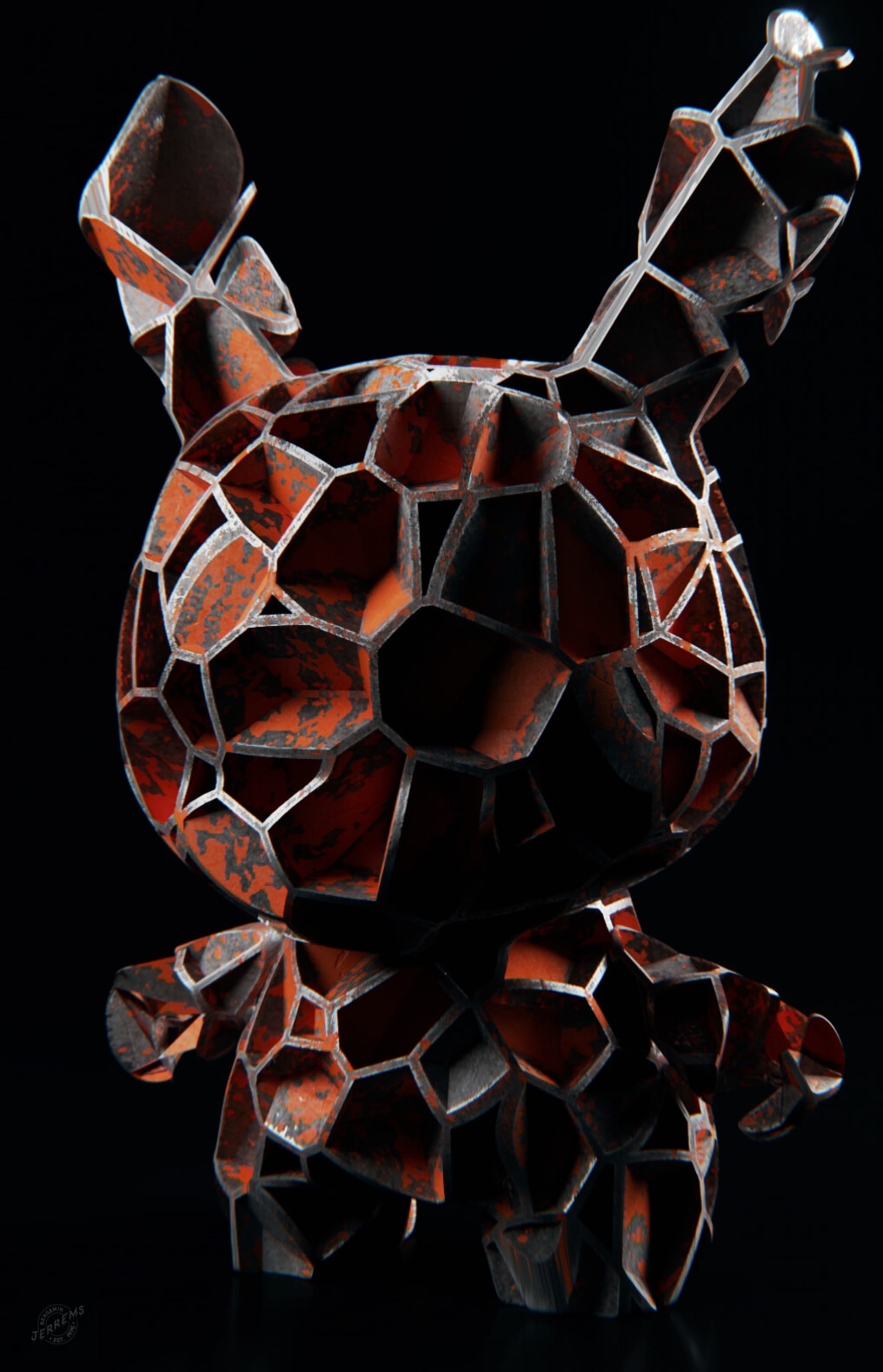
Rendered from Cinema 4D

Rendered from Cinema 4D
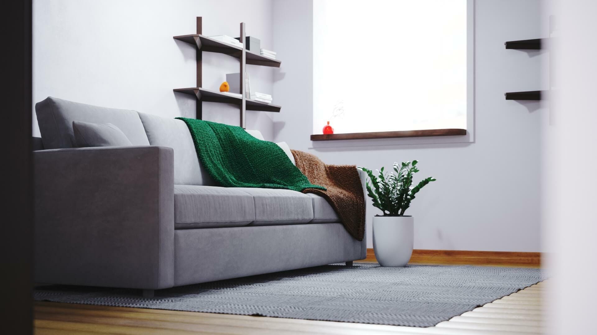
Rendered in 3ds Max
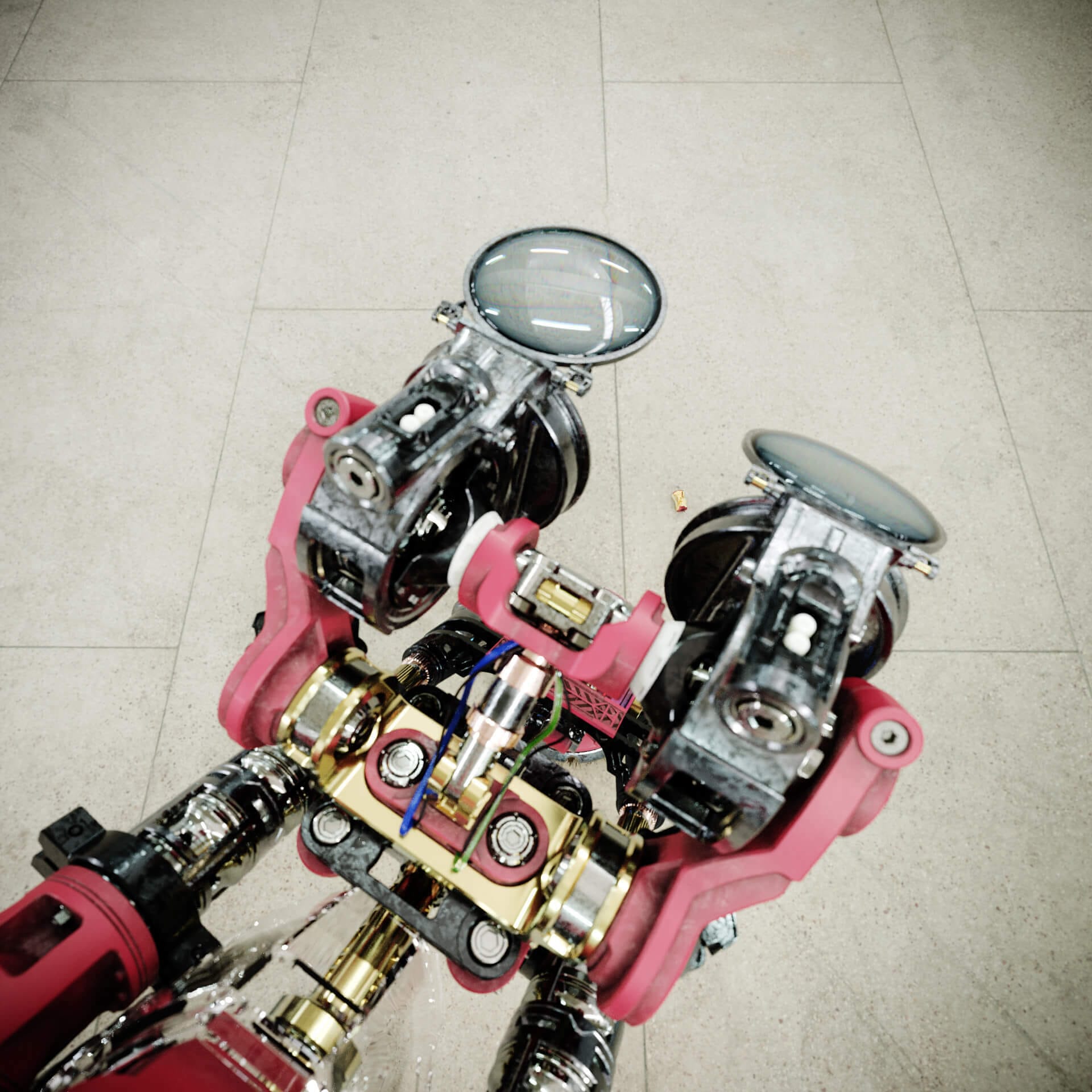
Rendered in 3ds Max
Why a new material?
The new material is about:
- An easier and more natural way to set up realistic materials.
- Increasing compatibility with material design software such as Quixel, Substance, etc. so that importing materials from those products is easier and more accurate.
- Increasing standardization with other render engines, to make it easier for those moving from another engine to Corona to understand and use the material.
- Ensuring you can’t accidentally create unrealistic “fake” materials that break some laws of energy conservation – however you set the parameters, the result will be (and look) realistic.
It is NOT about:
- Rendering faster
- Using less memory (or more memory, for that matter!)
REMEMBER
Everything shown here, especially the UI, is still under development. Also, screenshots have been taken at various stages of development so there may be changes in the UI between screengrabs, or between the images here and the current Daily.
Where do I find it?
Simply add a new Corona Physical Material, as shown below:
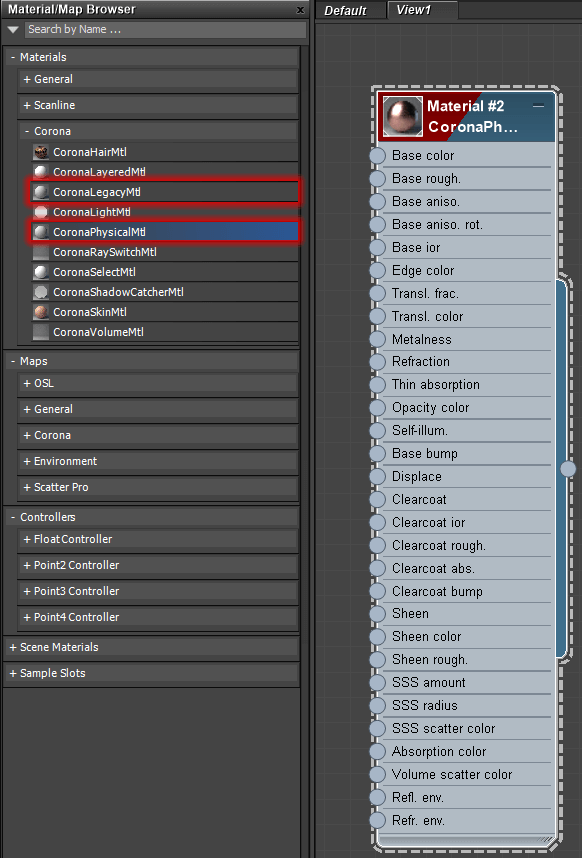
Where to find the new Physical Material (and the previous Corona Material, now renamed Corona Legacy Material)
Please note, if you want to use the previous default Corona material, it is still there and renamed as the Corona Legacy Material, highlighted above.
So what’s better about it, specifically?
Glad you asked! Here are the benefits that the new Physical Material brings.
Presets
The material comes with 34 presets you can choose from. These don’t include any maps of course, just settings in the material to give you a great starting point for many common types of materials that you’ll be using in your scenes.
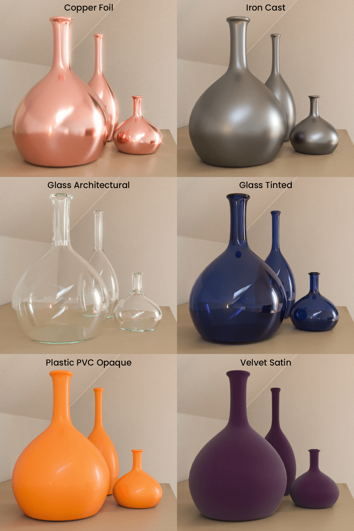
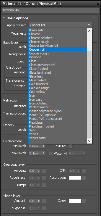
This one is clear
The Clearcoat is something that has long been requested in Corona. Prime examples are a coat of varnish over wood, or the final protective layer over the paint on a car. You can achieve a variety of effects using it:
First, no clearcoat at all, and using just the IOR in the base material. This result is perfect for a single reflective surface, e.g. our vase has been given a shiny coat of blue paint. The reflections directly follow the bump of the surface.
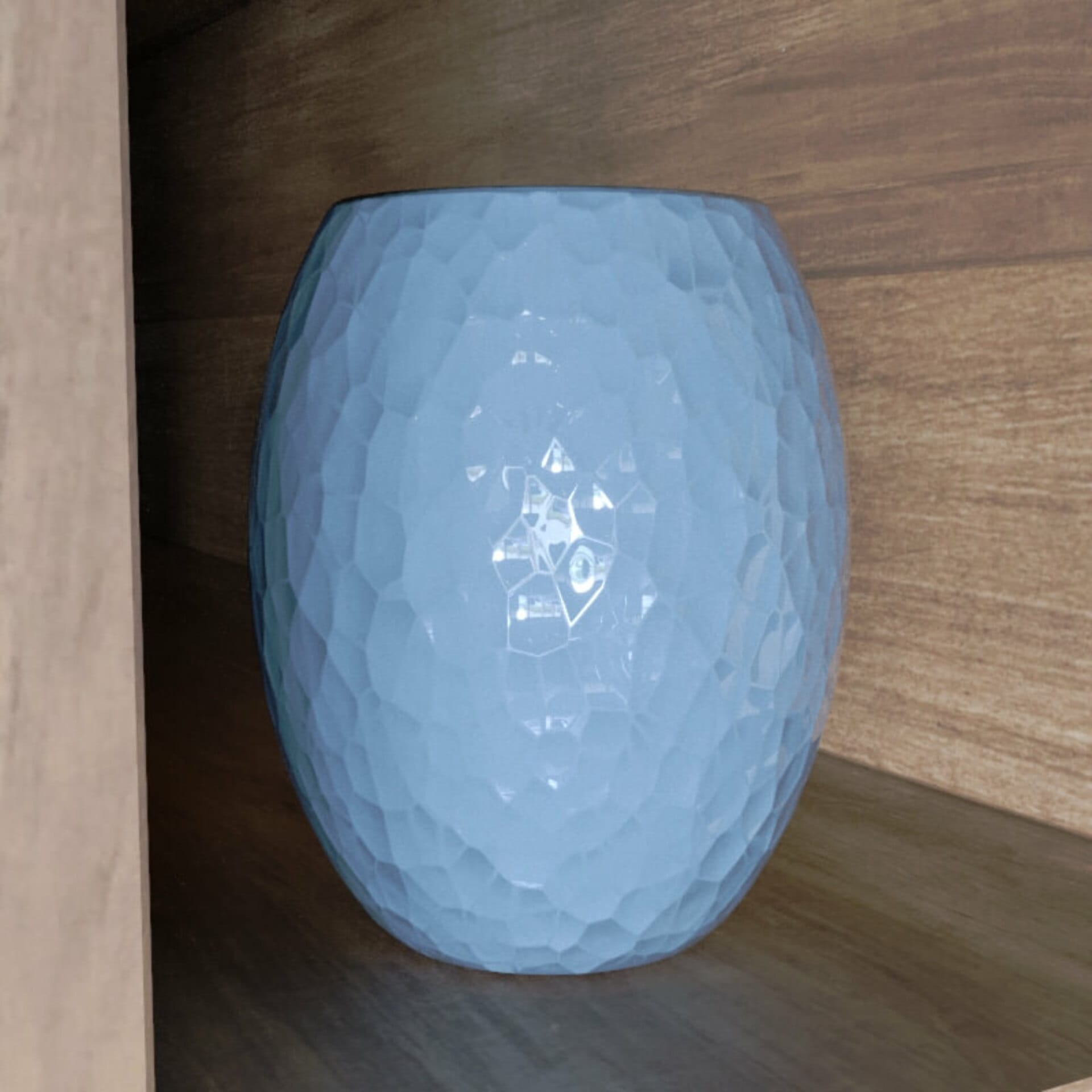
No clearcoat, and just IOR in the base layer
Now we can add a clearcoat, and give it no bump at all. The base layer underneath retains the bump, so this is like a super thick coat of varnish where its outer surface is smooth, but over a material that is rough. This now looks like a rougher surface – such as worked clay – with a smooth, thick coat of varnish over it. The reflections do not follow the bump of the underlying base layer:
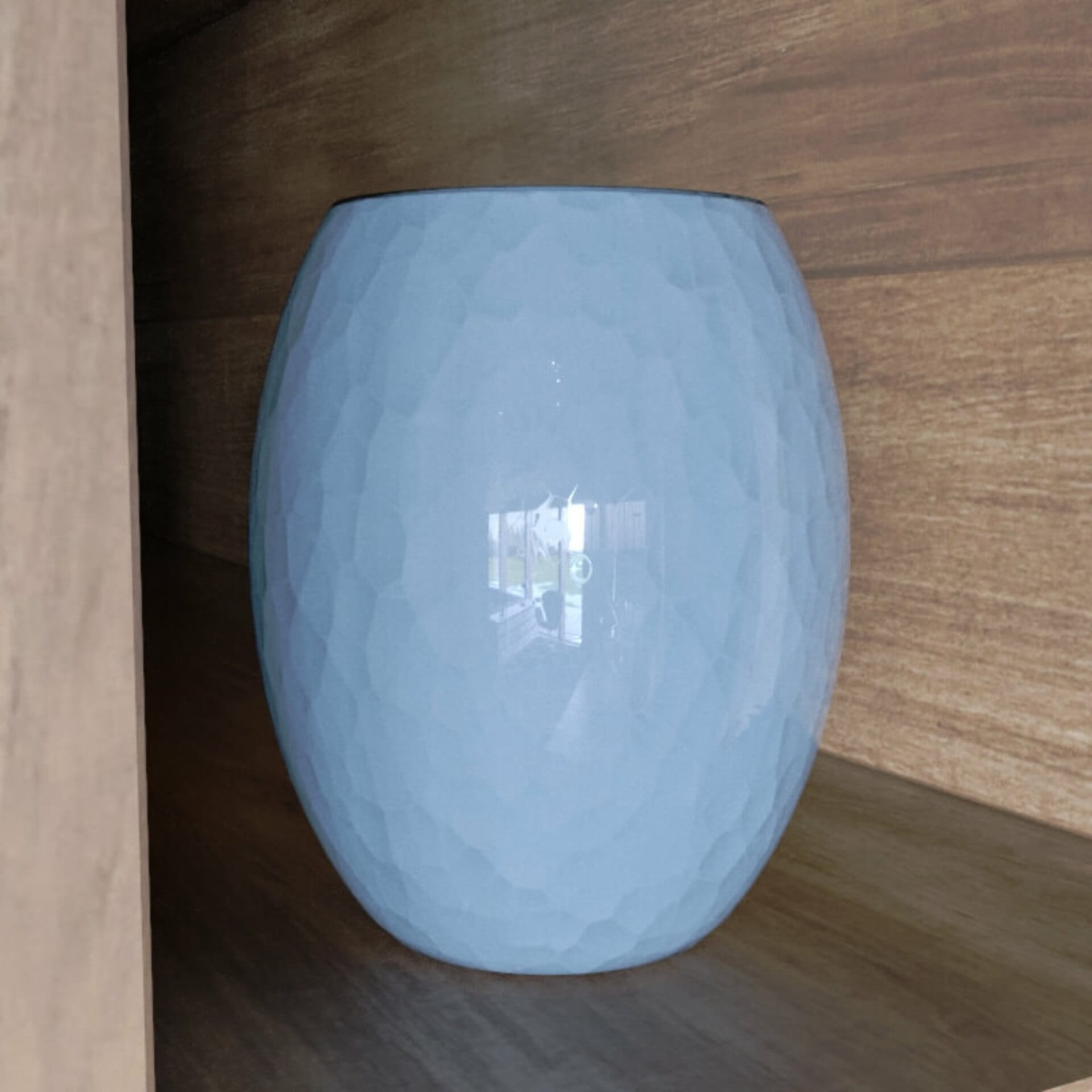
Clearcoat with no bump, over a base surface with bump
If we add the same bump map into the clearcoat, but reduce the bump strength, we get a result similar to a “semi-thick” layer of varnish, which partially follows the bump mapping but not as strongly as the base layer. Reflections are slightly distorted by the bump:
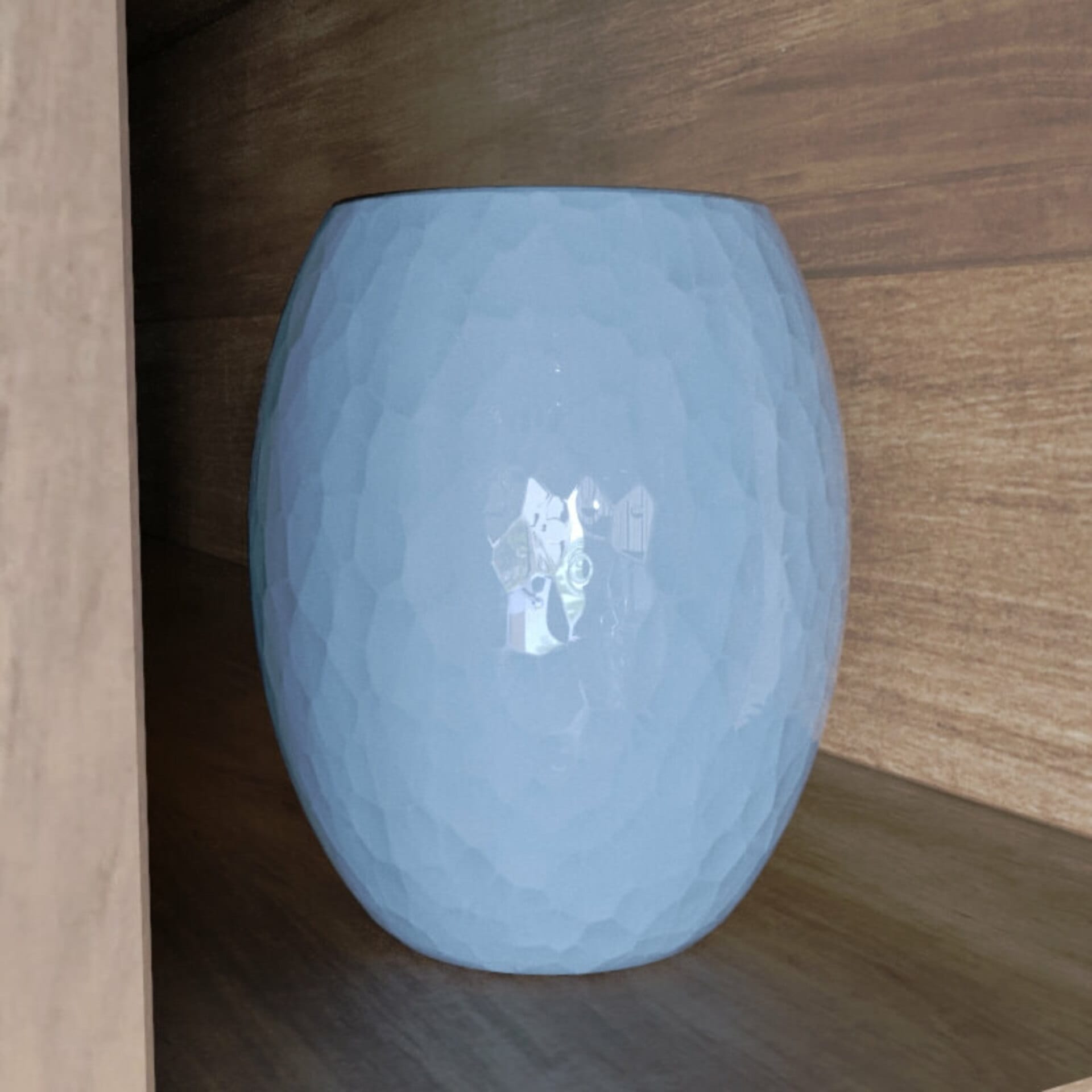
The same bump map is fed into the clearcoat and base layer, just with a lower bump strength in the clearcoat
Then you could give the clearcoat its own independent bump. This would be like a thick coat of varnish that is not totally smooth, e.g. rippled from not being an even thickness. In this case, reflections are distorted, but by a different bump than the underlying base surface:
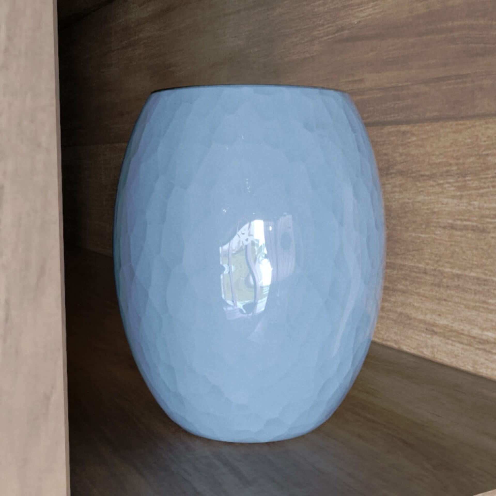
The clearcoat has its own bump map here, giving it a smooth rippled surface, like a thick layer of varnish that was not applied evenly
You could also blend the base layer bump map with another bump map before connecting it to the clearcoat bump, so that you get both some of the bump from the underlying base surface and an independent bump in the clearcoat, e.g. a “semi-thick” layer that softens the base surface features and also was not applied at an even thickess.
Soft and velvety
Sheen is another long-running request. This is what makes fabrics look like fabrics, with a different look at grazing angles, in particular things like velvet.

Sheen with no color

Sheen with a green color
Although in reality sheen is always a pure white color, the Physical material allows you to adjust the color of the Sheen effect – this allows for a quick and easy simulation of the effect of subsurface scattering in the fibers (which is why sheen effects in the real world do not always appear white).
To round out this section, one more example of the difference Sheen makes to a material:
Metal Detector
The shader features Metalness, a parameter which was not included in the Legacy material and is often used in materials exported from editing tools such as Quixel, Substance, etc.
For a simple example, here is a bucket without the Metalness being mapped (and using non-metal mode):
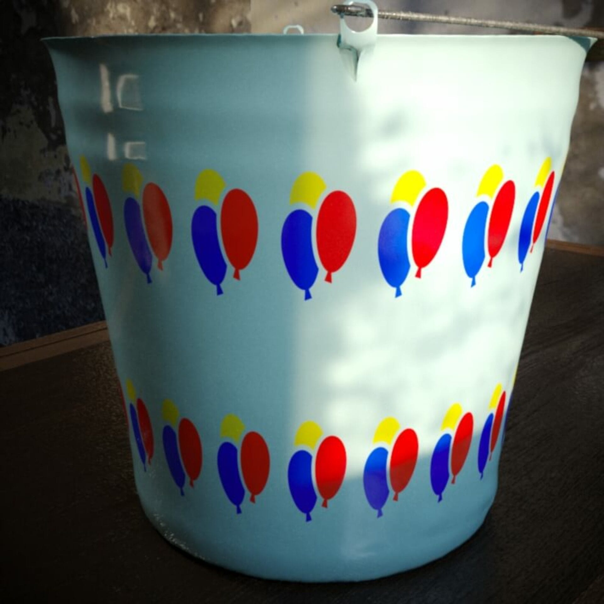
Non-metal material, no Metalness mapping
It’s easy to map only certain parts of the material to be metal, as seen below:
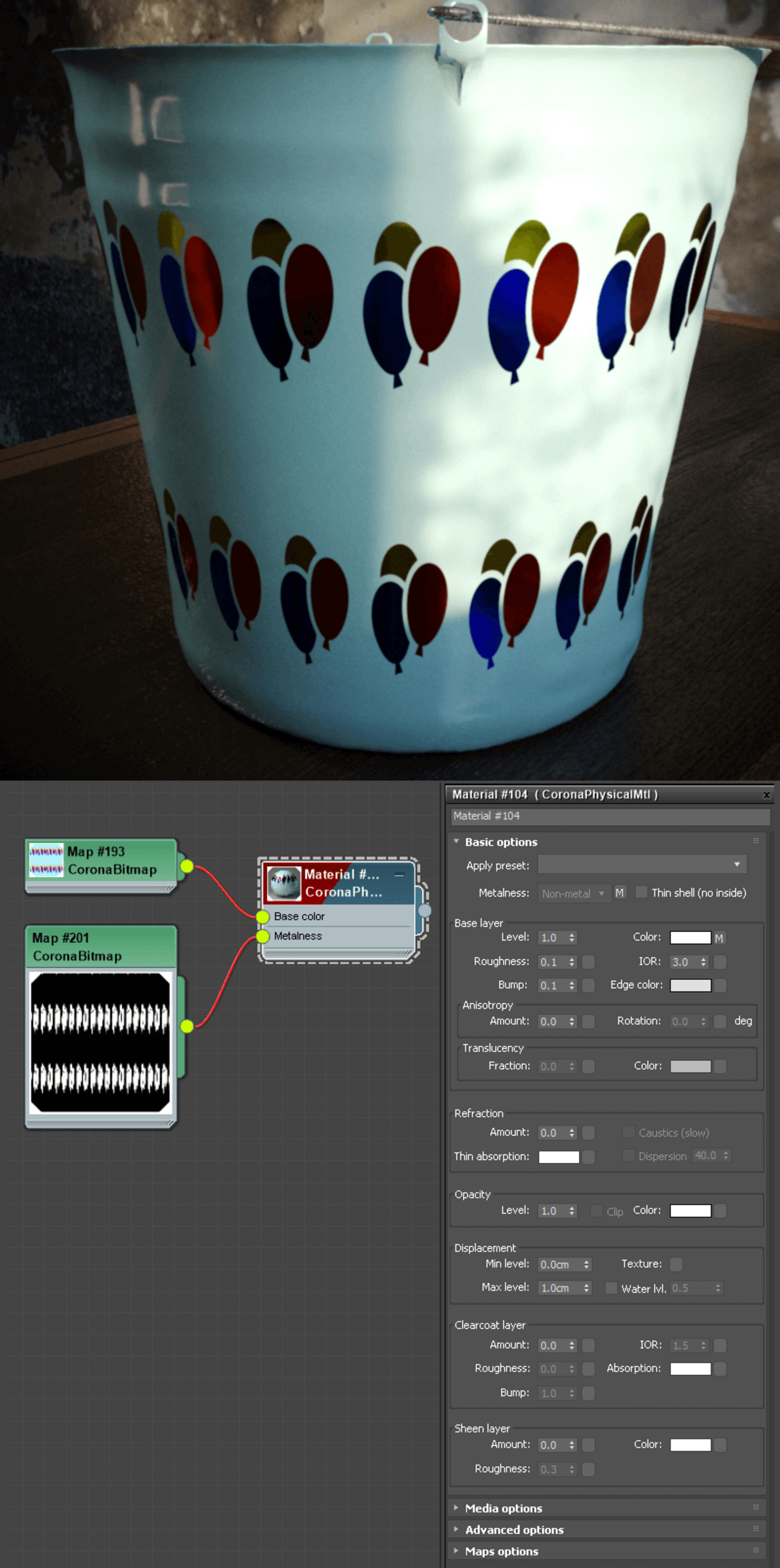
Still a non-metal material, but Metalness has been mapped so that some parts are metallic
Rough or Smooth? Have it whichever way you like!
By default, the shader uses Roughness mode, to match materials exported from many editing tools such as Quixel, Substance, etc. If you want, you can swap it back to the Glossiness mode so that it works the same as the Legacy material used to work.
Note that when you swap between modes, the value is updated automatically (e.g. a Roughness of 0.2 will be converted to a Glossiness of 0.8 when you change modes). Of course, this only applies if you are using an actual value in the parameter – if you are using a map in that slot, it is not modified in any way (as in the case of a map, it will already be either a Glossiness or a Roughness map, and you should set the mode according to the type of map you are using).
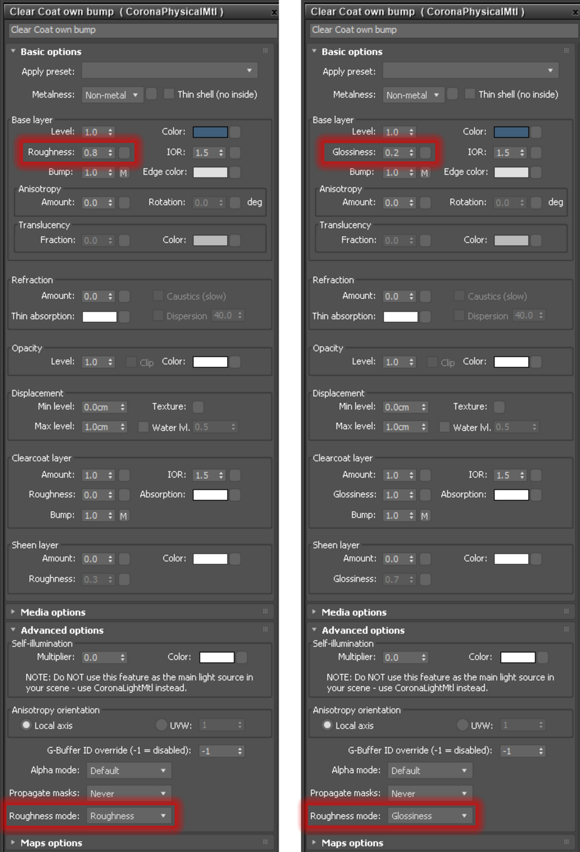
You can switch from Roughness (default) to Glossiness in the Advanced options. Note how the value is converted automatically if you switch
No more “impossible” materials
The shader has been carefully designed so that it lets you create realistic materials with no danger of creating strange, impossible, fake materials. Proper conservation of energy (and so realistic behavior) is built-in from the ground up.
Anisotropic – not just for reflection any more!
Anisotropy now applies to Refraction as well as to Reflection. This means that caustics, for example, can now be stretched in one direction or another, just like reflections, as seen in the example images below:
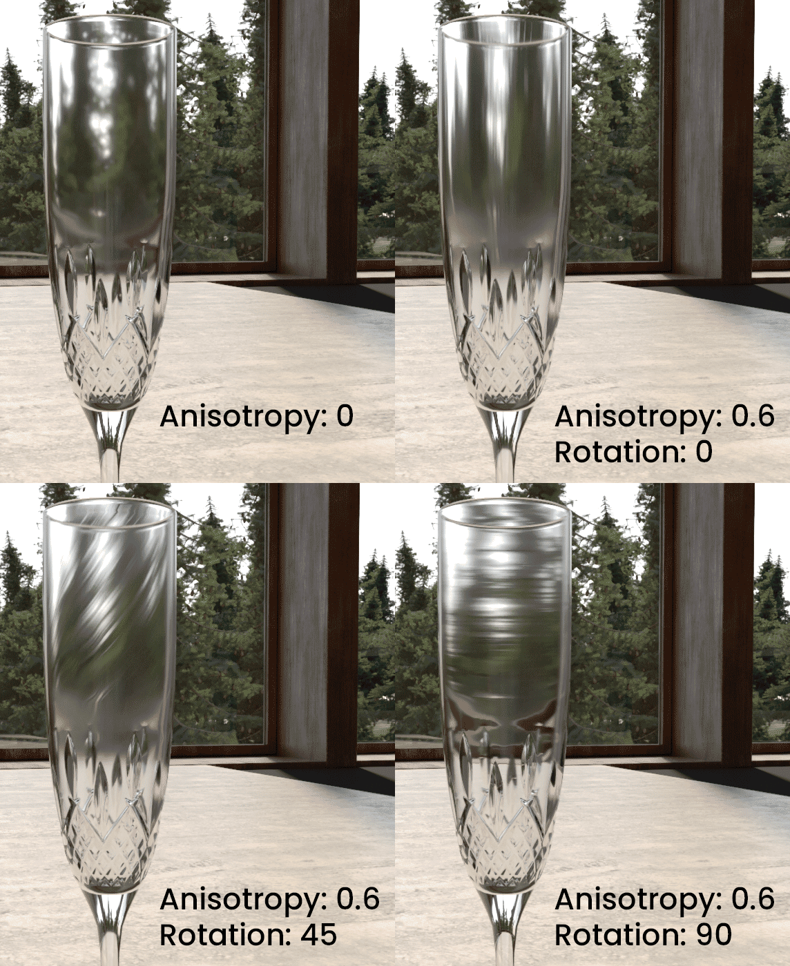
A roughness of 0.05, and the effects of anisotropy are clearly seen in the refraction
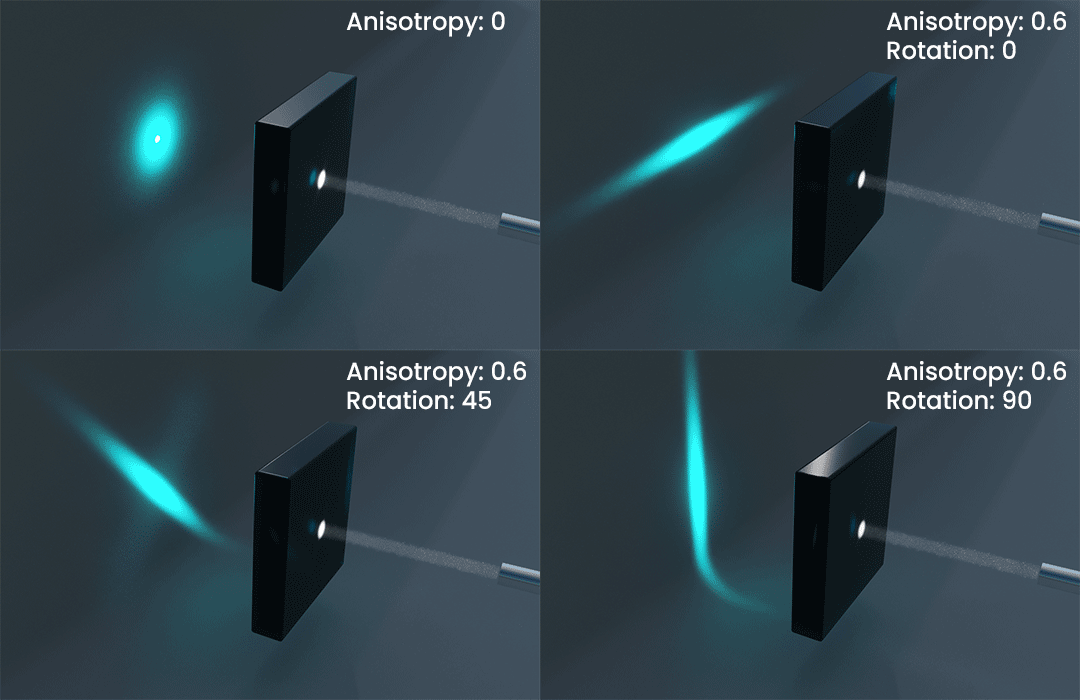
Refractive anisotropy affects caustics too
Compatibility, in summary
Have you ever created a great material in Quixel, Substance, or in other software, and then been frustrated in trying to figure out where to plug in that “metalness” map, or at having to remember to invert the “Roughness” map while remembering it connects to the “Glossiness” slot? Those days are gone!
Please note, some in-built export scripts or functions in other software may not yet be updated to export to this new Corona material, so selecting Corona as your chosen engine may result in the software automatically converting some properties to the old legacy approach. We hope this will change in time.
Convert me!
To help convert you to using the new material, we’re updating the Corona Converter so that it can translate Legacy material setups into Physical material set ups for you.
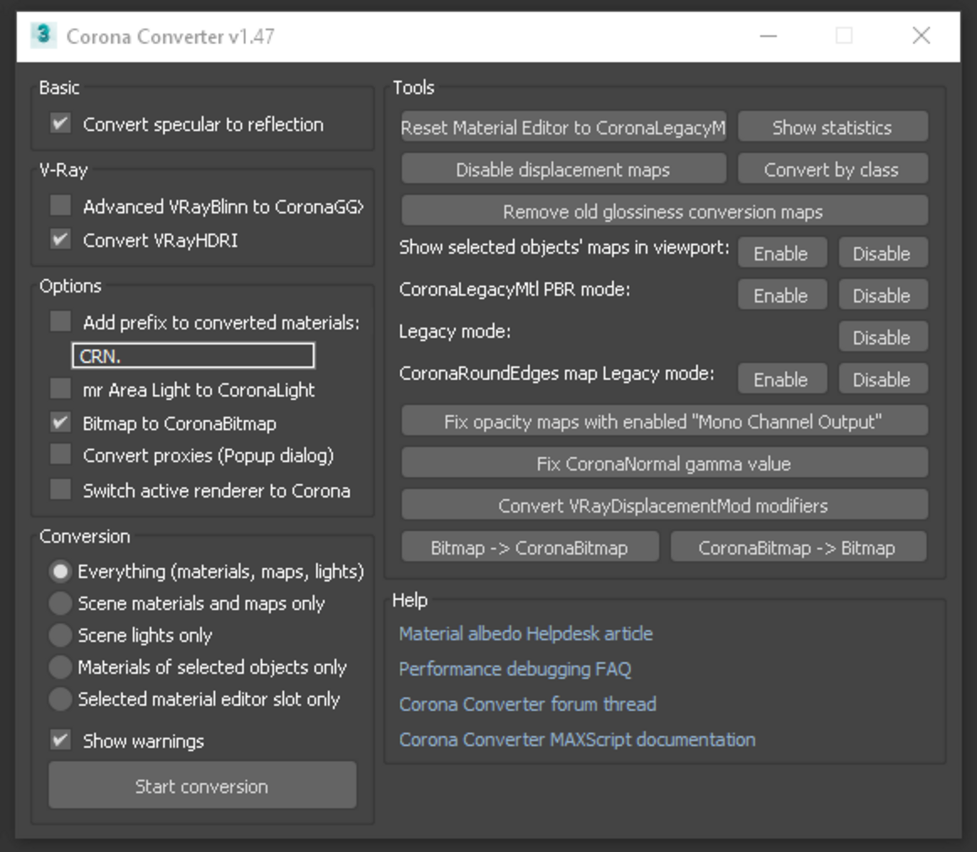
The UI of the Converter will not need to change much at all
This is still in development, but it is already working well with most materials. You can see an example below, using the Converter code from March 15th:
The two materials that show the largest changes are the ones using Translucency (the curtains, and the lampshade), but at the time this test was done, Translucency color was not an option in the Corona Physical Material (that option is added in the newly released Daily Build though!). If you look closely, the wine bottle on the table would also need some manual tweaking with this current build.
Also, please note that even in the final version of the Converter, not everything will convert 100% and some manual tweaking for some materials may still be required.
How do I do what I used to do?
For certain types of material, the workflow may be a bit different, beyond just parameters being in a different place in the UI. In this section, we’ll call out a couple of examples so you can get the hang of what has changed.
Reflection and Refraction IOR are linked now in the base layer, so how do I create glass with very strong reflection?
If you have settled on an IOR for a glass or water material, but the reflections do not feel strong enough to you artistically, then you can simply add a clearcoat layer and give it a higher IOR so that the reflections are stronger.
In the example below we used an IOR of 1.2 for the glass, and then added a clearcoat at a strength of 0.6 with an IOR of 1.52 on top of that in the image on the right:
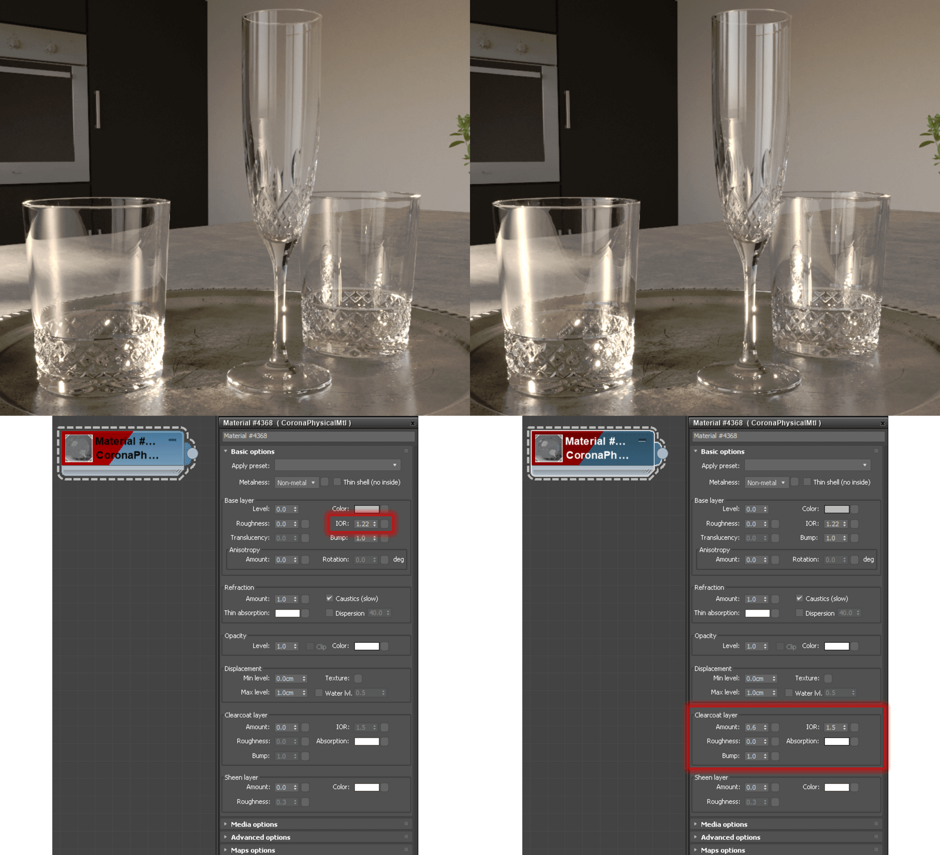
Just add clearcoat!
Note: While you can use Clearcoat to increase reflection intensity over a lower IOR Base material as above, you cannot reduce the reflection intensity of a high IOR Base material. This is an example of a constraint introduced by physical realism.
Of course you can also use clearcoat to add sharp reflections (low roughness/high glossiness) over a blurry glass or reflection (high roughness/low glossiness), to add a layer of smooth varnish or finish over a rough material, and all the other uses you can think of for clearcoat.
How do I create a material with Translucency, it appears to be greyed out?
To use Translucency, you need to enable “Thin mode” for a non-metal. Note that this also works with a texture plugged in to map the metalness amount, where Translucency will show for the non-metal areas.
You can see an example below, where we did also map the Metalness, so you can see how this works:
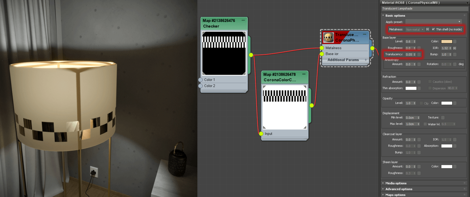
Enabling Thin Mode lets Translucency be used – in this case, Metalness was also mapped using a Checker map
Also, if you have used a previous Daily Build, you can now control Translucency Color separately (in earlier Builds, this was the same as the Base material color):
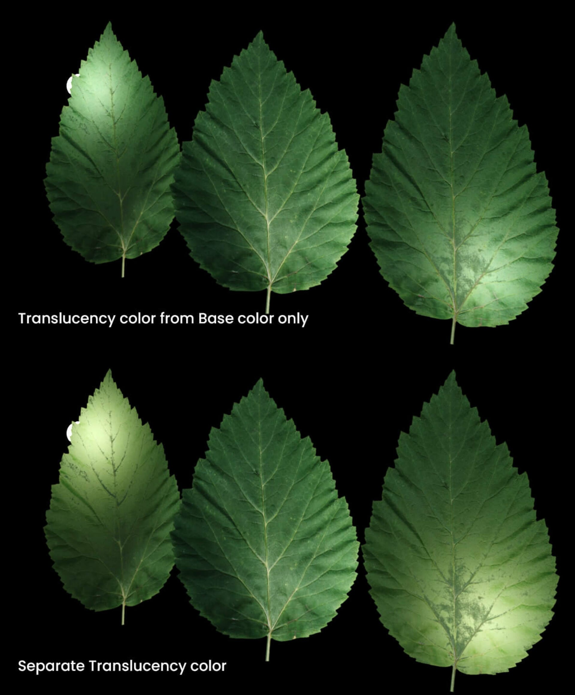
For those who used earlier Dailies – now you can set a separate Translucency Color
I have a totally black object, IOR is 1 and Roughness is 1, but it does not look completely black in the render, why is that?
This happens when an object is surrounded by or encased in another material with an IOR that is not 1 – for example, if your totally black object was submerged in water. The same effect can be seen with the Legacy material with an IOR of 1 and Reflectivity of 1 (the new Physical material never has a Reflectivity of 0, instead being controlled fully by IOR and Roughness, as happens with real world materials, which is why you may not have noticed this before depending on whether you realistically set up your Legacy materials, or “faked” it by turning Reflection to 0).
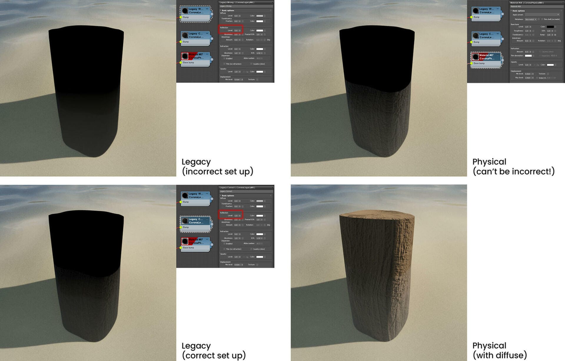
Remember the final IOR of a surface depends on any material it is immersed in / surrounded by
The reason for this is that the final IOR on a surface is in fact determined by the difference in IORs between that surface and the material that surrounds it, in other words a combination of the IOR of the object (in our test example, a log) and the IOR of the water. Since the IOR of the water is non-zero, the final IOR at this surface boundary is also non-zero (object IOR divided by water IOR).
You can more readily imagine this if you remember that while your water material may just be a plane or a cube in your 3D scene, according to the render engine and just like in reality, there is also a water surface around any objects inside it, it’s just that you didn’t have to model that!
How can I color reflections arbitrarily, e.g. using a map of some sort?
In normal use, the Physical material works like the real world, where reflections are always white, with very slight color variation at the grazing angles. To maintain this, there is no longer any “Reflection Color” slot in the material, unlike in the Legacy Material, and the Physical material correctly calculates color curves for metals based on the Edge color.
So, if we take this as our starting metal:
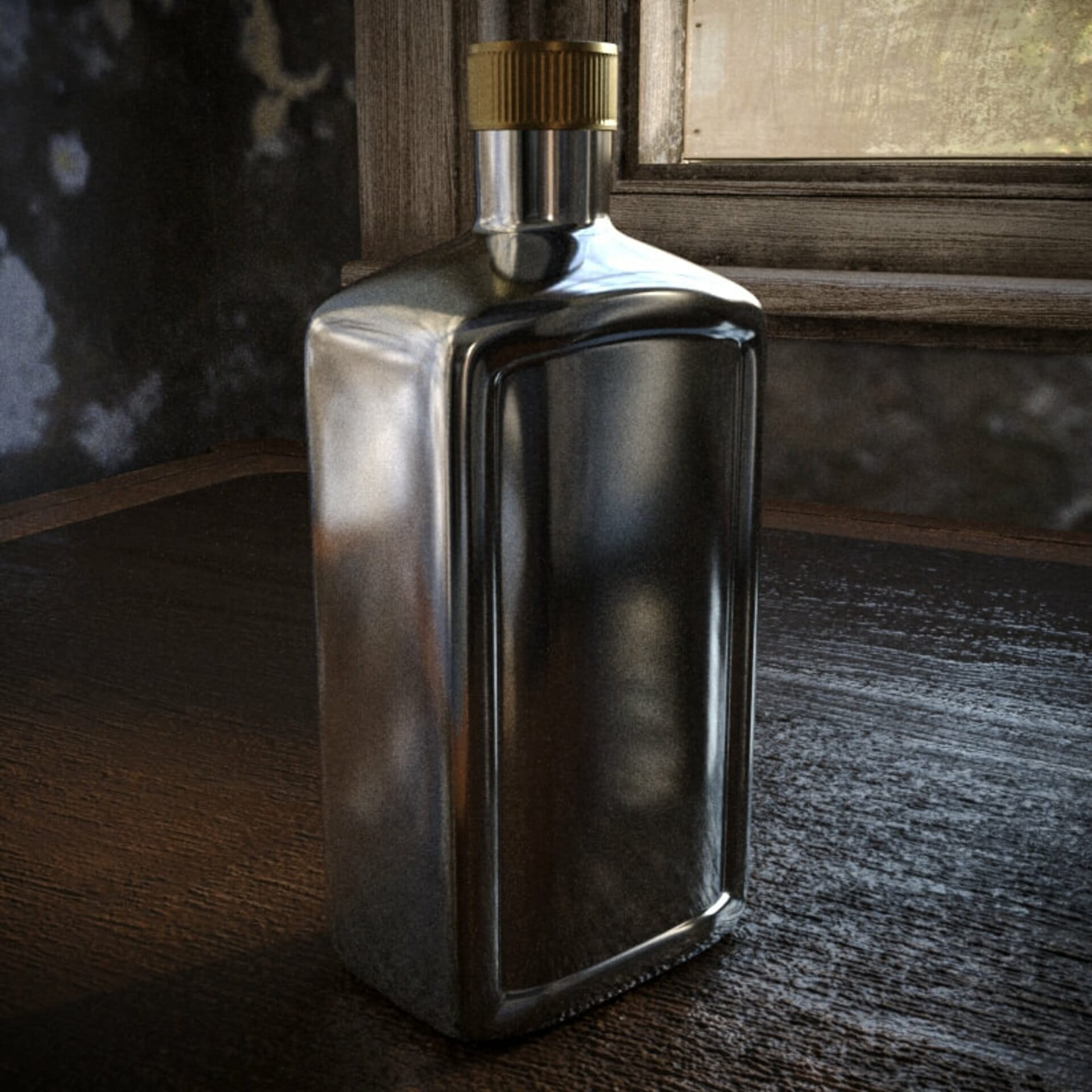
The starting metal, to which we want to add a “rainbow sheen” to (like a thin coat of oil)
In this case, we’re making our rainbow sheen by taking a Falloff map into a Corona Mix node, where it is combined with a Noise map in Multiply mode, and the result from that passed in to a Gradient Ramp:
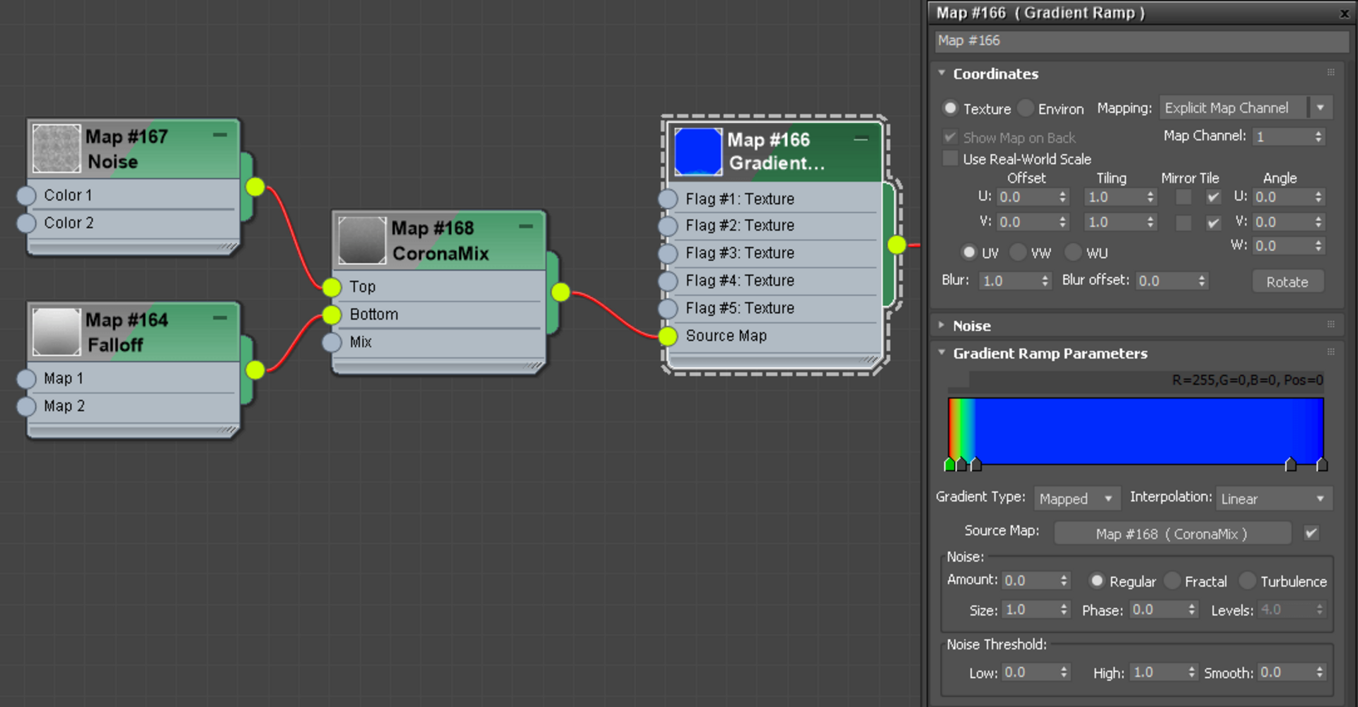
We could just place this into the Base Color, but then the result removes the grey appearance of the metal:

While interesting, it is too strong to look like a rainbow sheen. We could use this is a layer in a Layered Material, but is there a way without using the Layered Material?
We could control this by adding an extra Mix node, taking the rainbow sheen and blending it with a single color, before connecting it to the Base Color, but we want to try and avoid having extra nodes for this.
So another option would be to add our rainbow effect into the Edge Color instead. This may be what you are looking for – however, the effect is then also processed by only being at the edge (grazing angles) of the material, which may or may not be what you wanted. Plus, there is no control over the intensity of the effect, other than adding an extra node to mix the rainbow with a plain color before connecting it to the Edge color again.

Placing the rainbow falloff into the Edge color – notice how the effect is only visible at grazing angles, and surfaces facing us don’t show the effect at all
Or another option is to add it into the Absorption of the Clear Coat, setting the IOR for the Clear Coat to 1.001 so that it doesn’t add any reflection of its own, but instead just colors what is beneath it. We can easily use the Clearcoat’s Amount and IOR to determine how strong the effect should be, which is an advantage over using the Edge Color in the Base of the material. This gives the result below, and you can notice that the effect is not isolated to grazing angles, unlike when using the Edge Color in the Base of the material:
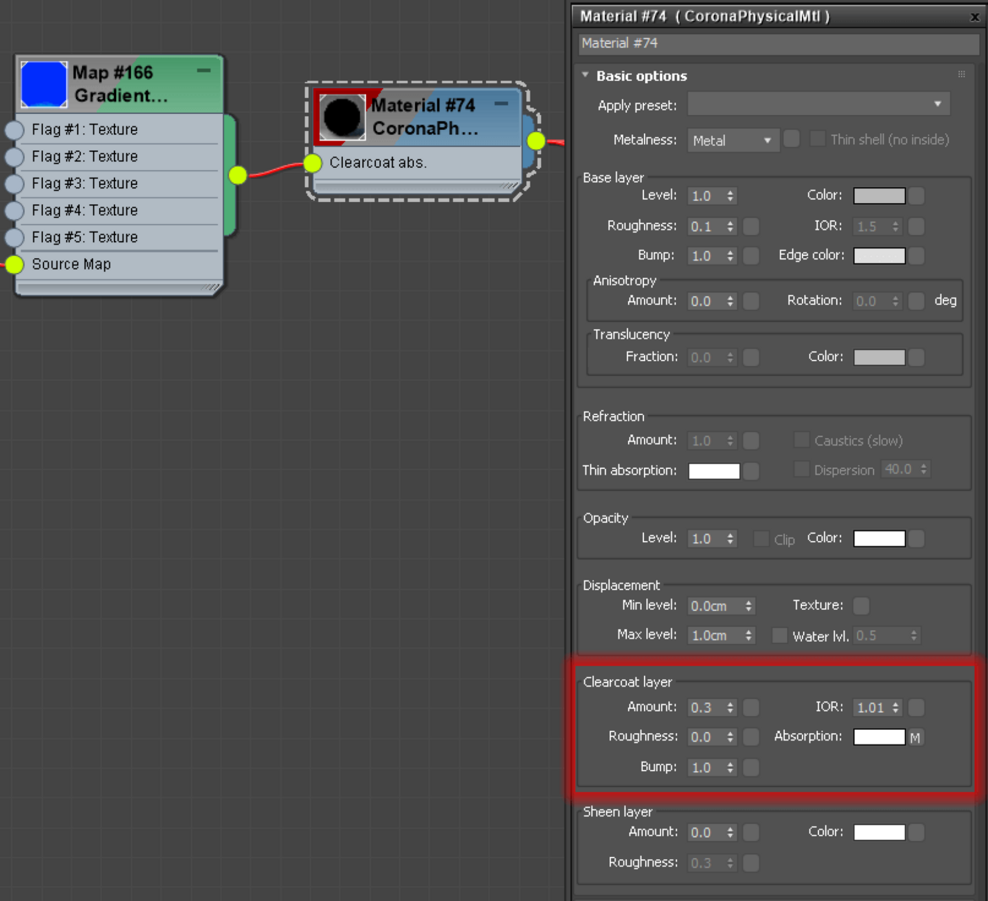

Using the Clearcoat Absorption color lets the effect stay visible when surfaces are facing us, and also lets us easily control the strength of the effect through the Clearcoat Amount, so we can keep it subtle
The same approach can be taken with non-metals too, e.g. to add this effect over glass, or perhaps water in a puddle.

The same Clearcoat approach to coloring reflection can be done with non-metals
Can we expect further functionality in future Corona versions (8 and onward)?
There are some things we are considering for the Physical material for future updates and improvements. Of course, if you test it now and give us feedback, it’s possible that there could be further improvements in Corona 7 itself too!
What else has been happening with Corona Renderer 7?
A lot! You can find full details by checking the 3ds Max or Cinema 4D changelog. We’re focusing purely on the Physical Material in this article because it is an important change to a workflow that is probably so familiar to you that it has become muscle memory, and we wanted to give you plenty of time to adjust before the final release!
Also, this was a lot of detail about just that one item, and we didn’t want the article to become an information overload – rest assured there are plenty of other changes coming in Corona Renderer 7.
That’s all folks!
And that’s it, all you need to know about the new Corona Physical material. “But wait!” I hear you say, “There’s even more writing down below – what about that?“
Well what follows is technical information that you do not need to know to use the material, but which may be of interest to 5% of users who are just curious about such things, or those of you who are having trouble falling asleep.
You don’t need to read it – and if you do, then you don’t need to understand it – in order to use the Physical material.
Meantime, please try out the new Physical material, and we welcome your feedback!
All the best,
The Corona Renderer Team

Technical Description of the new Physical Material (OPTIONAL!)
Remember, you don’t need to read or understand this to use the new Physical Material.
Clearcoat
The top most layer of our material is a clear-coat layer. It is implemented using isotropic GGX microfacet distribution with height-correlated Smith shadowing-masking function and it has an exact dielectric Fresnel term. The clear-coat has an amount parameter (strength of the layer), roughness (0-1), index of refraction (1-3), separate bump map and absorption color that influences all the layers below it.
Sheen
The next layer represents sheen. We use the model described in “Production Friendly Microfacet Sheen BRDF” by Estevez and Kulla (2017). For this layer we use simple Schlick Fresnel. The parameters are: amount (0-1 strength of the layer), color (normal-incident color as input to the Schlick Fresnel), roughness (0-1).
Base layer
For our base layer we use anisotropic GGX microfacet distribution with height-correlated Smith shadowing-masking function. We distinguish between metal and dielectric base (this can be specified either by metalness texture or by selecting just one base type). The common parameters for the base layer are: base color, roughness (0-1), anisotropy (-1 – 1), bump map
Metallic base layer
In the case of a metallic base layer, we already use the method “Bringing an Accurate Fresnel to Real-Time Rendering: a Preintegrable Decomposition” by Belcour et al 2020. This new method allows us to use the exact Fresnel for conductors (metals), while letting it be defined by two user-friendly parameters: base color and edge color.
Dielectric base layer
In this case the base layer uses an exact dielectric Fresnel term with controllable index of refraction (1-3) and is a combination of plastic and glass. This combination is controlled by the parameter refraction amount (0-1, 0 = pure plastic, 1 = pure glass). The plastic and glass materials differ in what happens with the light that is not reflected. For plastic, the remainder of the incoming light goes to the diffuse layer, which uses Oren-Nayar BSDF and has color defined by the base color parameter. For glass, the non-reflected light undergoes refraction.
Subsurface scattering (SSS)
The diffuse layer can be replaced by SSS (the user can specify a mixture of diffuse and SSS by an amount parameter 0-1). Subsurface scattering has a controllable bleed color and radius, while its albedo color is equal to the diffuse (base) color.
Volumetric scattering
The glass material can have associated volumetric scattering properties:
scattering albedo color and absorption color.
Thin dielectric layer
Note that the dielectric base layer can also be switched to thin mode, in which case the refraction of the glass material is replaced by opacity (with user defined absorption color), while the diffuse layer of the plastic material is split into diffuse reflection and translucency according to the translucency amount parameter (0-1). Note that no SSS or volume scattering is computed for thin mode.
Other stuff
Besides these layers, the user can set independent emission (which is not influenced by any of the layers), opacity and displacement.
Combining layers
The physical material is made in such a way that it is both energy conserving (no additional energy is created with the exception of an emission layer) and energy preserving (no energy is lost). The light that is not reflected by the clear-coat layer goes to the Sheen layer. What is not reflected by the sheen layer is split to metal and dielectric base layer according to metalness. Finally, light that reaches the dielectric base layer is split among plastic and glass materials (according to refraction amount). Note that our material ensures reciprocity, so it works correctly with bidirectional light transport algorithms.

That’s all folks! (again)
This time it really is the end of this article, extra technical stuff included. Remember, you can find out about Daily Builds for 3ds Max and for Cinema 4D, and we welcome your feedback!
All the best!
The Corona Team (again)


